Build an End-Fed Half-Wave Antenna From a Kit
Project by Frank Bontenbal, PA2DKW
Process photos by Bob Inderbitzen, NQ1R
Please note: This kit is available from ARRL. The original assembly instructions are available from the manufacturer, HF Kits.
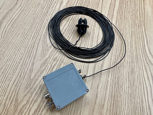
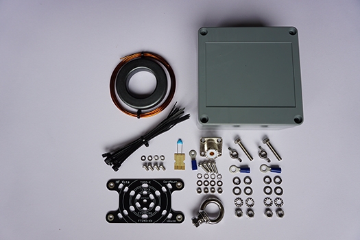
To help new hams prepare for the exciting world of HF opening up during Cycle 25, ARRL has partnered with HF Kits to bring you this easy-to-build four-band antenna kit: an end-fed half-wave (EFHW) antenna. Unlike the dipole antenna, which is comprised of two quarter-wavelength wires and fed at its center, the EFHW is a half-wavelength antenna with the coaxial cable for your transceiver attached at one end. It has become popular with portable operators because it’s very simple in its construction and deployment. This antenna, which works on 10, 15, 20, and 40 meters, has a very high impedance of around 2,500 Ohms. The kit includes the parts needed to construct a 49:1 impedance matching network, which will transform the impedance to 50 Ohms, which will suit most transceivers. This article details the construction of the transformer.
Tools
- Drill and drill bits (1/8 to ¾ in step bit, ¼ inch bit, 13/64 inch bit, 9/64 inch bit)
- Pliers
- Wire cutter
- Sharp knife or sandpaper
- Soldering iron and solder
- Screwdriver
- Marker
Materials
End-Fed Half-Wave antenna kit from www.arrl.org/shop (all materials and parts mentioned in this article are included in the kit).
Prepare the Enclosure
Step 1
Drilling through the enclosure is easy! Measure and take your time, but the enclosure is not difficult to drill. A standard drill and drill bits will work. You may also choose to use a step drill bit for the larger hole.
Mark and drill a 5/8 inch hole for the coaxial connector that will attach to the enclosure. This is a large hole, and it’s easiest to create it with a step drill bit. Drill the hole ½ inch from the top of the enclosure, which will make fastening the connector to the enclosure easier (see 1).
1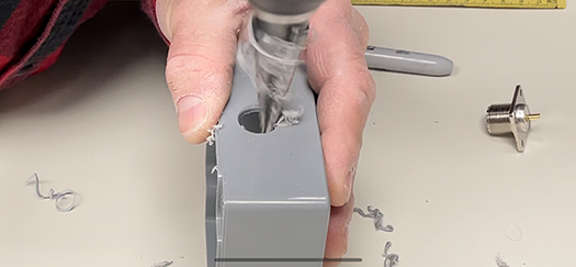
Step 2
Put the coax connector into the hole and use a marker to mark the four holes for the screws (see 2A and 2B). Drill the four fastening holes with a 9/64 inch bit. Next to where the coax connector will be installed, drill a 13/64 inch hole for the counterpoise connection.
2A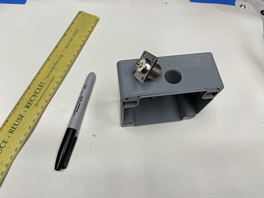
2B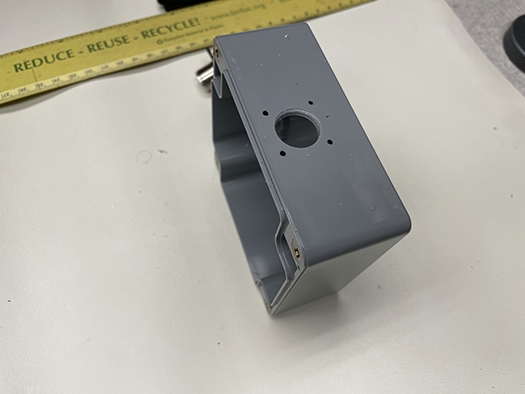
Step 3
On the opposite side of the enclosure, mark and drill the holes for the antenna connection (use a 13/64 inch bit) and strain relief (use a ¼ inch bit). It is especially recommended to provide strain relief for antennas that will be installed for the long term. We recommend placing the stainless-steel eye for the strain relief in the center, but you can place it to your own liking.
Step 4 After drilling all the holes, attach the coax connector and counterpoise connection (see 3A) and strain relief and long wire antenna connection (see 3B). Tighten each of the screws (see 3C). When attaching the bolts on the inside of the box, use two tooth lock washers, placing one above and one below the cable lug to prevent it from rotating later when you’re connecting the antenna wire or counterpoise. Use pliers to remove the blue plastic part of the cable lug.
3A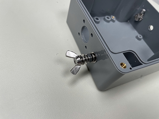
3B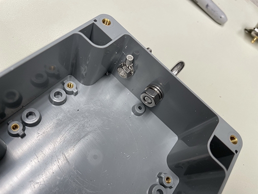
3C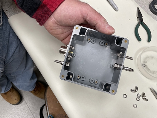
Make the Impedance Transformer
Step 5
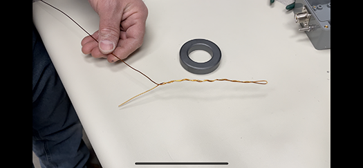
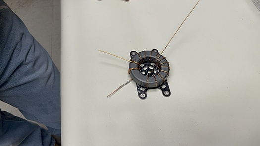
Fold about 8 inches of the enameled copper wire in half and lightly twist the first 6 inches to hold it together (see 4). Make sure to not twist the copper more than a few turns, because this might create strange effects in the transformer at a later point.
4
Step 6
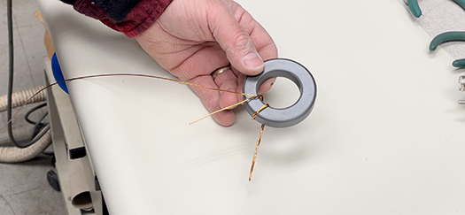
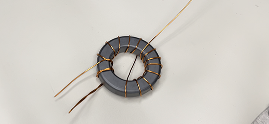
Find the point where the two pieces of wire become one, and place this on the toroid. Wrap the double part twice around the core. Then wrap the other 12 windings as shown in 5A and 5B, crossing the wire over to the other side of the toroid after the sixth wind.
5A
5B
Step 7
Cut the loop of the double winding wire end. This creates two loose wires. With a sharp knife or sandpaper, remove the insulation from the winding wire close to the core. Do this carefully, because if the wires do not make good contact, the antenna will not work. Then wrap the wires around each other a few turns and solder them. Now the toroid is ready to be fixed onto the special toroid mounting plate (see 6). Do this with the zip ties included in the kit.
6
Finishing Up
Step 8
Trim the wires of the transformer to an appropriate length and screw the toroid mounting plate into the housing.
Step 9
A 100 pF capacitator of can be soldered into place over the primary side of the transformer, to compensate for any (unwanted) secondary capacity (see 7). This will mainly be noticeable on the higher bands; 15 to 10 meters. If you will not be active on 15 to 10 meters, you may leave the capacitor out.
7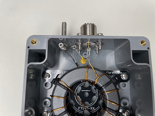
Step 10
Solder the primary side of the transformer to the chassis connector socket and the counterpoise connection (see 8). Make sure that the insulation on the enameled copper wire is completely removed. You can easily scrape off the insulation with a knife or sandpaper. Make sure to do this properly and carefully, so a good solder connection can be made.
8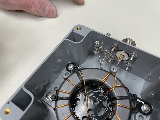
Step 11
After completing the primary side, solder the secondary side of the transformer to the antenna connection. Place the included toothed spring washers above and below the M5 cable lugs inside the housing. This will prevent the bolt from turning when the connection to the antenna wire is made.
Step 12
You can test the impedance transformer by using a resistance of about 2,500 Ohms (for example, using a 2K7 resistor) on the ground of the coax connector and antenna connection. The SWR meter should show a standing wave ratio of approximately 1:1.5 or lower. It is important that an induction-free resistor is used and that the connecting wires are as short as possible. Usually the SWR meter does show some reflected power with this test. It’s also possible to test with a half wavelength of wire.
Step 13
Put the cover on the transformer (see 9; a rubber gasket and screws for the enclosure are included), attach the counterpoise wire, antenna wire, and coax.
9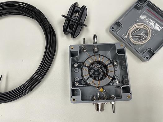
Step 14
You can test the antenna using the SWR meter in your transceiver or an external SWR meter connected to the feed line between the transceiver and the impedance transformer. Use a low amount of power to complete the test. A standing wave ratio of approximately 1.5:1 or lower is a good match! Try different configurations of the antenna before beginning to trim the antenna wire, a couple of inches at a time, to achieve a low SWR on each of the bands.
Applications for this Transformer
It’s easy to come up with many antenna varieties that you can match with this 1:49 impedance transformer. In theory, it’s possible to connect any half wavelength or a multitude of these to the transformer in order to get a resonant antenna. Here are a few examples:
- 16 feet of wire is a half wave for the 10-meter band.
- 33 feet of wire is a half wavelength for the 20-meter band and two times a half wavelength for the 10-meter band.
- 66 feet of wire is a half wavelength for the 40-meter band, but also a full wave for the 20-meter band, a double full wave for the 10-meter band, and three half-wavelengths for the 15-meter band.
Parts (included)
-
P65 enclosure 100 x 100 x 55 mm with weather sealant and screws 4x
Toroid Amidon FT240-43
Toroid mounting plate
Stainless steel M3 6mm screws 4x
Stainless steel M3 split lock washer 4x
Winding wire 1.0 mm
Cable ties 8x
100 pF capacitor 2kV
SO-239 chassis mount connector
Stainless steel M3 bolt 12mm 4x
Stainless steel M3 nut 4x
Stainless steel M3 washer 4x
Stainless steel M3 tooth washer 4x
M3 cable lug
M5 cable lugs 2x
Stainless steel (A4) M6 strain relief
Stainless steel M6 nut
Stainless steel M6 washer
Stainless steel M6 lock washer
Stainless steel M5 bolt 25mm 2x
Stainless steel M5 wing nut 2x
Stainless steel M5 nut 4x
Stainless steel M5 washer 4x
Stainless steel M5 tooth lock washer 4x
Stainless steel M5 split lock washer 4x -
66 feet (approx. length) of strong, flexible, and low weight wire
2x Stainless steel cable clamp
1x end insulator
1x cable lug 5mm
1x Heat shrink sleeve for cable lug
Publications & Online Store >> Product Notes >> End-Fed Half-Wave Antenna Kit
